Main Panel
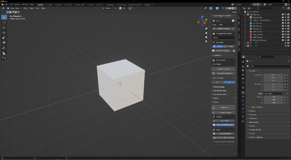
The main SEUT panel holds the vast majority of the functionality of the addon. It can be found on the right side of the 3D Viewport (button marked in green) of Blender and opened by pressing N while the cursor is within the viewport.
Space Engineers Utilities
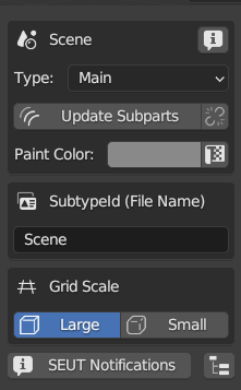
Scene
This is the name of the scene name that is synced with the SubtypeId.
Type
Allows selection of scene type. Depending on the scene type, a scene is exported differently and certain functionality becomes available. Valid types are:
- Main - This is the default scene type. Most of your scenes will be of this type.
- Subpart - This scene contains a subpart that is part of a
Mainscene. - Character - This scene contains a character model. It is treated in a specific way by the exporter to make it appear correctly ingame.
- Character Animation - This scene contains either a character pose or character animation and is treated differently by the exporter.
- Planet Editor - This scene can be used to create a Space Engineers planet with. Only one can exist per BLEND file.
Update Subparts
Updates all subparts linked into the current scene with the changes made in their individual scenes.
Unlink Subparts
Unlinks all subparts from the current scene.
Paint Color
The paint color that is applied to all materials supporting recolorability in the current scene.
UV Grid Overlay
Replaces all materials in the scene with an UV-checker grid overlay that allows comparison of material tiling / texel density.
SubtypeId
The SubtypeId is your model’s unique identifier. It is written both into the SBC as well as written into the filename of the exported models. In scenes of type Subpart, Character and Character Animation it only defines the filename as no SBC is created for these on export. The SubtypeId is furthermore used to mark all collections belonging to a scene so that they can be differentiated from same-function collections in other scenes.
UNDO-functionality to revert to before it appeared.Grid Scale
This option sets your Blender grid to align to the size of either large or small grid within Space Engineers. The grid is set to half the size of either to allow you to correctly place the blocks on world origin in Blender. This setting is also used to by the addon to adjust what gets written to the SBC as well as to scale the bounding box so make sure it’s set to the correct scale for your block.
SEUT Notifications
This button will open up the SEUT Notifications screen. It is the place where SEUT logs everything happening within this file, and informs you of errors. Should an error appear, this button will appear in red.
By default, because SEUT relies on collections to organize your model, you will be switching between collections fairly often. However, generally you’ll only really want to look at the contents of a single collection at a time. Enabling this option will hide all non-active collections automatically. Thus, whenever you click on another of the SEUT collections, it will be unhidden and all other collections will be hidden in turn.
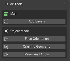
Quick Tools
QuickTools must be enabled in the addon’s Addon Preferences to display in the SEUT Main Panel. The appearance of the QuickTools panel differs depending on what type of SEUT collection you currently have selected and whether you are in OBJECT or EDIT-mode.
The QuickTools panel provides commonly used action sequences as single button presses and makes commonly used tools available in once convenient place.
Main
If you have the Main-collection selected, it will display a Main-section and an Object Mode-section.
Add Bevels
Adds bevels of a given amount to all selected objects and enables Harden Normals.
Object Mode
The Object Mode-section is the same no matter which collection is selected.
Face Orientation
Toggles the face orientation overlay on or off.
Origin to Geometry
Moves the origin of the object to the centerpoint of its geometry.
Mirror And Apply
Mirrors all selected objects on a given plane, then applies transformations and inverts all faces. When an object is mirrored using the mirror modifier and then has its transformations applied, all its faces will be inverted. By using this button, it then uninverts the faces automatically.
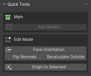
Edit Mode
The Edit Mode-section is the same no matter which collection is selected.
Face Orientation
Toggles the face orientation overlay on or off.
Flip Normals
Flip the normals of all selected faces.
Recalculate Outside
Makes the face normals of the selected object point either outside or inside the mesh.
Origin to Selected
Sets the origin of the current object to the selected vertice, edge or face.
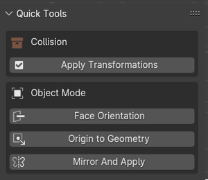
Collision
If you have the Collision-collection selected, it will display a Collision-section and an Object Mode-section.
Apply Transformations
Applies all transformations to objects with rigid bodies by first removing the rigid bodies, then applying transformations, then adding the rigid bodies back. This circumvents an issue where transformations cannot be properly applied while an object has an active rigid body.
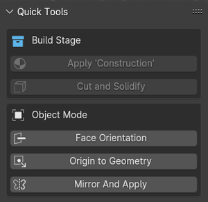
Build Stage
If you have a Build Stage-collection selected, it will display a Build Stage-section and an Object Mode-section.
Apply ‘Construction’
Applies a corresponding Construction-type material to all material slots of all selected objects.
Cut and Solidify
Uses Inset faces with given distance, deletes the inner faces and then applies a Solidify modifier with given thickness and applies it. This results in a scaffold-alike look of the given object.
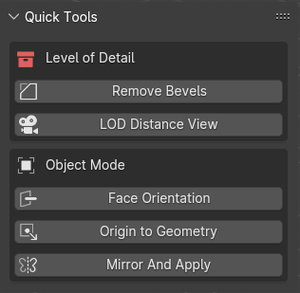
Level of Detail
If you have a LOD-collection selected, it will display a Level of Detail-section and an Object Mode-section.
Remove Bevels
Removes the Bevel-modifiers of all selected objects.
LOD Distance View
Visualizes the distance set for the active LOD-collection by spawning a camera with standard game FOV at the corresponding distance. This allows the user to preview, how large an object would be displayed on screen ingame and thus adjust the detail of the model accordingly.
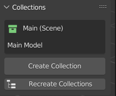
Collections
Recreate Collections
This button will create the various collections SEUT uses to organize your models within the active scene. The addon requires you to place all objects it should handle within one of these collections.
Create Collection
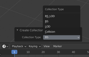
This button will allow you to create new SEUT collections of specified types.
- BS_LOD - A Build Stage Level of Detail (BS_LOD) collection.
- BS - A Build Stage (BS) collection.
- LOD - A Level of Detail (LOD) collection.
- Collision - A collection containing collision objects, assigned to another collection in the scene.
Collision
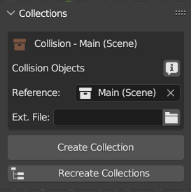
If a Collision-type collection is selected in the Outliner, you can set the collection it is associated with in this panel.
You can also define an external HKT-file that is used in place of the objects in your collection.
LOD / BS_LOD
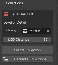
If a LOD or BS_LOD-type collection is selected in the Outliner, you will be able to set their LOD Distance in this panel.
Bounding Box
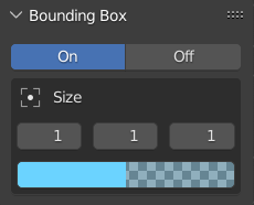
The bounding box indicates the size of the block inside Space Engineers. Be sure to adjust it so all of your block is within it (unless in some special cases).
Size
Use the X, Y and Z-properties to adjust the size of the bounding box. These values are written to the SBC.
Color
Click on the colored bar to customize the color of the bounding box overlay and its transparency.
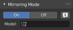
Mirroring Mode
Mirroring Mode is used to set up block mirroring options within Space Engineers. Its results are written to the SBC. Refer to the Mirroring Tutorial for more details.
Model
This links to another scene, which is used for mirroring display in place of an instance of the normal model contained within the Main-collection of the current scene.
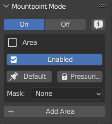
Mountpoint Mode
Mountpoint Mode allows the user to define the areas of the block that attach to other blocks. Mountpoints are divided by the block’s Sides. Each Side can have multiple defined Areas that are valid attachment points. Refer to the Mountpoint Tutorial for more details.
Enabled
By utilizing this toggle, it’s possible to disallow mounting in a specific location on the side of a block.
Default
Set a Mountpoint Area’s side as the one the block is first attempted to be placed on.
Pressurized
Whether a mountpoint on a door block stays pressurized when the door is opened.
Mask
Masks determine which blocks' mountpoints can be mounted onto this mountpoint area.
- None - No mountpoint mask is used.
- Protrudes - The geometry behind this mountpoint protrudes out of its block bounds.
- Narrow - Used for window edges and other narrow surfaces at the side of the block.
- Thin - Used for catwalks and other thin mountpoints at the side of the block.
- Central - Mountpoint in the center of a side but not its edges, used on Sensors, Cameras, Interior Lights etc.
- Custom - Define custom values for the Exclusion and Properties Mask.
Add Area
Adds a new area to the selected empty’s side that can be repositioned and rescaled (rotation is not saved).
Icon Render Mode
Icon Render Mode allows the easy rendering of icons for a block.
Render
This button will save the current camera view as a render to the specified Output Path. It will only render the scene’s Main-collection.
Zoom
This property adjusts the camera’s distance from origin.
Location
These properties allow for moving the camera and lighting setup from the point of origin.
Rotation
These properties allow for the rotation of the camera and lighting setup around the point of origin.
Color Overlay
Untoggling this property will remove the blue tint from the resulting icon render.
Resolution
Sets the resolution in pixels of the resulting render.
File Format
Sets the file format of the resulting image.
Output Path
Sets the path to which the render will be saved when Render is pressed.
Copy Icon Render Options
Copies the icon render options set in this scene to all other scenes.
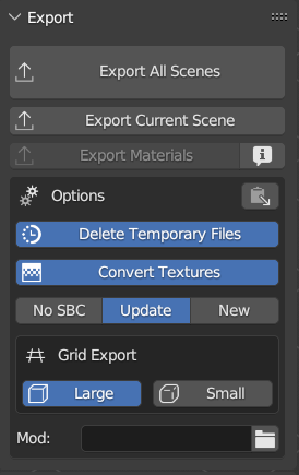
Export
Export All Scenes
This button will iterate through all scenes and their collections within the BLEND-file and export them one by one.
Export Current Scene
Exports all collections within the current scene.
Export Materials
Exports all materials defined within the BLEND-file to an XML-library.
Copy Export Options
This button copies the current Export Options to all other scenes within the BLEND-file.
Delete Temporary Files
By default, the only files resulting from export are the SBC and MWM files, as all intermediary files are automatically cleaned up. Untoggling this option will prevent these temporary files from being cleaned up and thus allows for debugging.
Convert Textures
Whether or not SEUT should convert textures to DDS and place them in the mod folder on export, should they not be present or older than the image files linked within the material.
SBC
This selection controls whether a SBC file is generated on export. It is enabled by default but once the initial SBC has been adjusted, a new export is usually not needed.
Large
This toggle controls whether the current scene is exported to large grid.
Small
This toggle controls whether the current scene is exported to small grid.
Mod
The main directory of your mod (where the Data-folder is placed in).
Export Folder
The directory to export your model to within your mod folder. Must contain Models\ in its path to be eligible. Set this to directly export into your mod’s directory.
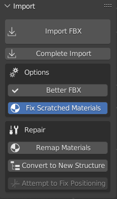
Import
Import FBX
This button allows for the import of FBX files. Imported geometry is automatically processed further, thus it is heavily recommended to use this button over the default Blender FBX import option.
Complete Import
This button allows you to select a target FBX file and then attempts to also import all associated models into the scene and sort it into the collections - LODs, BS, BS_LODs as well as the main model.
Better FBX
This option allows the use of the alternate FBX-importer and only shows if it is available.
Fix Scratched Materials
SDK models have a scratched texture mapped to their bevels by default - but it does not appear ingame because it is replaced on MWM conversion. That method does not work for SEUT. This option (active by default) will replace these materials with their non-scratched counterparts automatically on import.
Remap Materials
This button replaces all materials in the BLEND-file with the materials in the linked MatLibs, if they have common names.
Convert to New Structure
This button should be used first thing when opening BLEND-files that have been set up with the old 2.7x (Harag or Balmung’s) Blender plugin. It will convert the old file structure to the new structure used within SEUT.
Attempt to Fix Positioning
This button attempts to fix the positioning of an imported FBX object as well as its child objects as some of the vanilla FBX files, on import, can be misaligned due to issues in Blender’s FBX import code.
Make Blender compatible
This button converts the names of bones in the BLEND-file to a Blender-compatible format.
Make SE compatible
This button converts the names of bones in the BLEND-file to a Space Engineers-compatible format.

